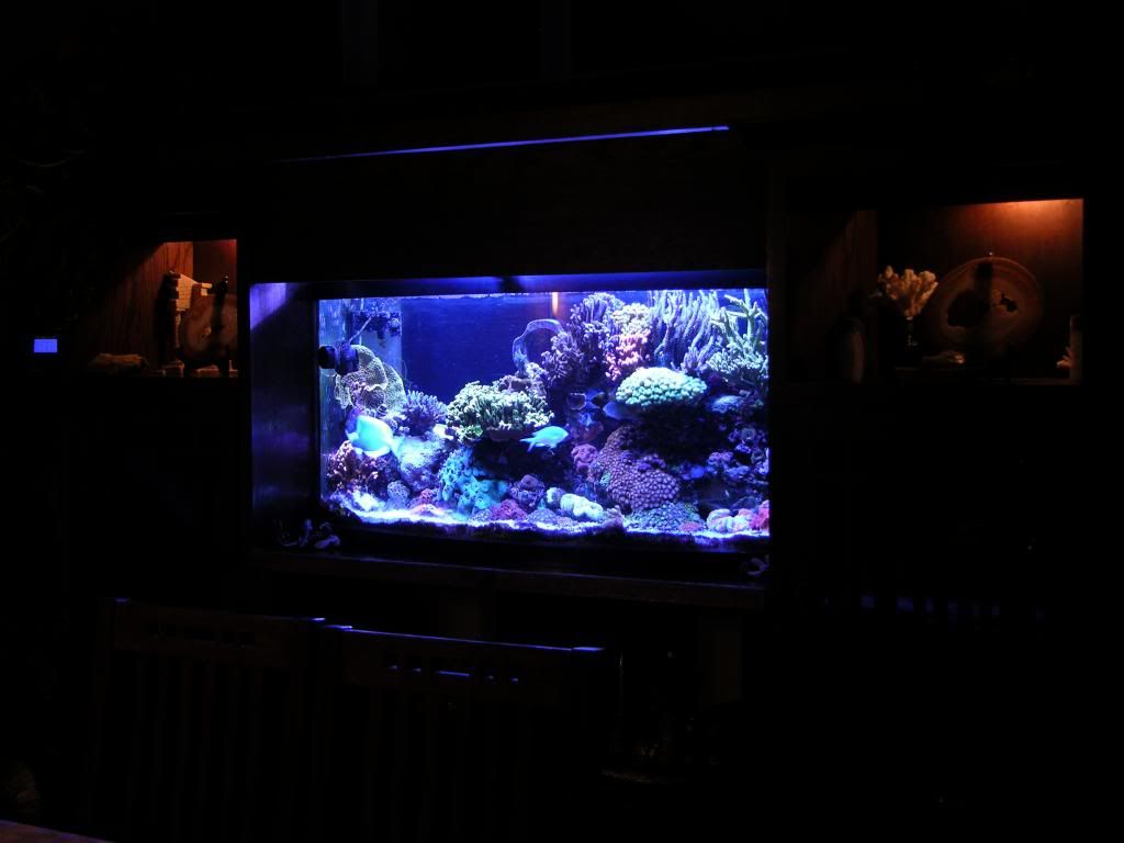
DyM Reef Journey

DyM

Sting ray
M.A.S.C Club Member
#41
[size=+2]NEPTUNE APEX SET UP & DESCRIPTION[/size]

[highlight]Be careful if you cut and paste, this coding works find for me, but each set up is different so be careful!! [/highlight]

[highlight]Post questions on code to another thread instead of this build thread please. [/highlight]

If you have questions about my setup, ask away, if it's about yours, pls make a separate thread or PM me.

Apex Name: ApexNome

Firmware: 4.20_CA12

Listing generated: 01/10/2013 08:12:59

PROGRAM:
// Program Variable Speed Ports (VSP) use profiles to control these ports, like programming for outlets go on or off, these VSP control intensity 0-100% for pumps and LED lights. For my reef, I have 2 VSP’s for pumps, and 2 VSP for LED.

[ Tunze_L ] ( base_Var1 ) // Goal is to have random variable flow, the different profiles are explained in that section, but the variety is to provide the randomness.
Program Type: Advanced
Display Icon: Up/Down Arrows //This should go away, be an option to remove
Program:
Set Night_L // Set is the default. If no other profile is valid, the pump will be in Night_L

If Time 09:00 to 09:29 Then Dusk_L​
If Time 09:30 to 21:59 Then Day_L​
If Time 22:00 to 22:30 Then Dusk_L​
If Outlet v_FlushTimer = ON Then FlushA​
If Outlet v_Random = ON Then Random_L​
If Outlet v_TunZtest = ON Then Day_L2​
If Power EB4_6 Off 000 Then Night_L // If there is a power outage, the Tunze pumps are on a UPS, so they will work for more than an hour. I know the tank water will be lower, since the main return pump will be off. I do not want the water being pushed so strong it may make waves that will splash over the edge.

If Power EB8_4 Off 000 Then Night_L​
If FeedA 005 Then Feed​
If FeedB 005 Then Feed_2​
If Outlet v_OVERFLOW!! = ON Then Night_L // There are float switches that prevent the tank from overflowing. My tank does not have a built in overflow, so there’s the inverted ‘U’ tube that takes the water from upstairs, down to the sump/fuge. If any part of that overflows or floods, the float switch triggers and the return pump shuts off. Same as a power outage, this lowers the intensity of the pump so there are no waves splashing over the edges.


[ Tunze_R ] ( base_Var2 )
Program Type: Advanced
Display Icon: Left/Right Arrows
Program:
Set Night_R
If Time 09:00 to 09:29 Then Dusk_R
If Time 09:30 to 21:59 Then Day_R
If Time 22:00 to 22:30 Then Dusk_R
If Outlet v_FlushTimer = ON Then FlushB
If Outlet v_Random = ON Then Random_R
If Outlet v_TunZtest = ON Then Day_R2
If Power EB4_6 Off 000 Then Night_R
If Power EB8_4 Off 000 Then Night_R
If FeedA 005 Then Feed
If FeedB 005 Then Feed_2
If Outlet v_OVERFLOW!! = ON Then Night_R​

[ LED_White ] ( base_Var3 ) // These are the two Variable Speed Ports (VSP)to control intensity 0-100% for LED lights. For my reef, I have 2 VSP’s for pumps, and 2 VSP for LED.
Program Type: Advanced
Display Icon: Sun
Program:
Set OFF
If Time 09:30 to 10:00 Then OFF // My White LED’s have a few burnt out (my error) so when I try to vary the intensity, a portion of the lights blink. This is why I have on/off instead of calling on profiles to define the conditions of intensity.
If Time 10:01 to 11:45 Then ON
If Time 11:46 to 12:16 Then OFF
If Time 19:50 to 20:59 Then OFF
If Time 21:00 to 21:59 Then OFF​

[ LED_Blue ] ( base_Var4 )
Program Type: Advanced
Display Icon: Left/Right Arrows
Program:
Set OFF
If Time 09:30 to 11:59 Then AM-BLU_1 // The Blue LED’s call on these profiles to define the conditions of intensity. They ramp up and down depending on the time and profile.
If Time 12:00 to 19:49 Then AM-BLU_2
If Time 19:50 to 21:59 Then PM-BLU_1
If Time 22:00 to 22:30 Then PM-BLU_2​

[ SndAlm_I6 ] ( base_Alarm ) // I need to spend more time defining these and using them for items such as if PH rises or falls to a certain point or if I need a reminder
Program Type: Advanced
Display Icon: Sound B
Program:
Set OFF
 

DyM

Sting ray
M.A.S.C Club Member
#42
If you have questions about my setup, ask away, if it's about yours, pls make a separate thread or PM me.

[ SndWrn_I7 ] ( base_Warn )
Program Type: Advanced
Display Icon: Sound A
Program:
Set OFF
If Outlet Return_Down = OFF Then ON​

[ EmailAlm_I5 ] ( base_email )
Program Type: Advanced
Display Icon: Email // The last condition that is true, is what will be on the email/text. It is therefore important to prioritize.
Program:
Set OFF
If Temp > 81.5 Then ON // I need to add more conditions here. For example, a bad probe will read 60, need to know about that. Also, need to add the probe in the sump – for low and high conditions
If Temp < 76.4 Then ON
If Outlet Return_Down = OFF Then ON // I guess this is a failsafe, if the outlet if off, I want to know. I however think the below conditions cover this, so I have never seen this error come through.
If Outlet v_OVERFLOW!! = ON Then ON // There are float switches that prevent the tank from overflowing. My tank does not have a built in overflow, so there’s the inverted ‘U’ tube that takes the water from upstairs, down to the sump/fuge. If any part of that overflows or floods, the float switch triggers and the return pump shuts off.
If Outlet v_Sump_High = ON Then ON // This is a second float switch downstairs in the sump. If the switch triggers, the level in the sump is too high, and something is wrong.
If Outlet v_FloatIssue = ON Then ON // This was set up to test the connection between the Apex and the float switch module. Switches fail open, if this detects an open condition, either the connection is lost or the switch is bad. I however find this also detects when power is turned back on. Also, power outage but I think since I’ve added the below, they will be what the power outage text or email will say/
If Power EB4_6 Off 000 Then ON // This is upstairs on a different circuit than EB8_3
If Power EB8_3 Off 000 Then ON // This is downstairs on a different circuit than EB8_4 &EB4_6
If Power EB8_4 Off 000 Then ON​

[ PlugBlueLED ] ( 3_1 ) // This is the outlet that LED drivers plug into. . For 5W Blues. The reason I have it turn off is the leds are on to a certain extent, even though I have profiles stating the LED’s should be off. Once I fix the whites, I’ll research this more. The good thing, it looks kind of like Moon lighting during the night.
Program Type: Advanced
Display Icon: Sun
Program:
Fallback OFF
Set OFF
If Time 08:00 to 24:00 Then ON
If Temp > 81.5 Then OFF​

[ PlugWhiteLED ] ( 3_2 ) // This is the outlet that LED drivers plug into. For 5W Whites
Program Type: Advanced
Display Icon: Sun
Program:
Fallback OFF
Set OFF
If Time 08:00 to 22:10 Then ON
If Temp > 81.5 Then OFF​

[ Colling_Fans ] ( 3_3 ) // This controls a 12V relay that turns cooling fans on when the temp is higher than 77.3 – this works well.
Program Type: Advanced
Display Icon: Fan
Program:
Fallback ON
Set OFF
If Temp > 77.3 Then ON​

[ HQI_250W_L ] ( 3_4 ) // This is the 250W Metal Halide ballast.
Program Type: Advanced
Display Icon: Light B
Program:
Fallback ON
Set OFF
If Time 11:00 to 21:00 Then ON
If Temp > 81.5 Then OFF
Min Time 015:00 Then OFF​

[ PlugBlue2LED ] ( 3_5 ) // This is the outlet that LED drivers plug into. For Uv and 3W Blues
Program Type: Advanced
Display Icon: Sun
Program:
Fallback OFF
Set OFF
If Time 08:00 to 24:00 Then ON
If Temp > 81.5 Then OFF​
 

DyM

Sting ray
M.A.S.C Club Member
#43
If you have questions about my setup, ask away, if it's about yours, pls make a separate thread or PM me.

[ CollingFans2 ] ( 3_6 ) // This controls a 120V cooling fan at the top of the hood; on when the temp is higher than 77.3 – this works well.
Program Type: Advanced
Display Icon: Thumbs
Program:
Fallback ON
Set OFF
If Temp > 77.3 Then ON​

[ Reserve_3_7 ] ( 3_7 )
Program Type: Advanced
Display Icon: Light A
Program:
Fallback ON
Set ON
If FeedA 005 Then OFF​

[ HQI_250W_R ] ( 3_8 ) // This is the 250W Metal Halide ballast.
Program Type: Advanced
Display Icon: Light B
Program:
Fallback ON
Set OFF
If Time 11:00 to 21:00 Then ON
If Temp > 81.5 Then OFF
Min Time 015:00 Then OFF​

[ Return_Down ] ( 4_1 ) // This is the Little Giant return pump
Program Type: Advanced
Display Icon: Thumbs
Program:
Fallback ON
Set ON
If Outlet v_OVERFLOW!! = ON Then OFF // There are float switches that prevent the tank from overflowing. My tank does not have a built in overflow, so there’s the inverted ‘U’ tube that takes the water from upstairs, down to the sump/fuge. If any part of that overflows or floods, the float switch triggers and the return pump shuts off.


[ Heater_Down ] ( 4_2 ) // This is a strip with three 100w heaters.
Program Type: Advanced
Display Icon: Thermometer
Program:
Fallback OFF
If Temp > 77.3 Then OFF
If Temp < 77.2 Then ON
If TempDwn > 77.4 Then OFF
Defer 000:10 Then OFF
Defer 000:10 Then ON
If Outlet v_OVERFLOW!! = ON Then OFF​

[ SO4_Reactor ] ( 4_3 ) // This is the sulfur reactor
Program Type: Advanced
Display Icon: Moon
Program:
Fallback ON
Set ON​

[ 4_4 ] ( 4_4 )
Program Type: Advanced
Display Icon: Up/Down Arrows
Program:
Fallback OFF
Set OFF

[ T5_sump ] ( 4_5 ) // This is lighting for the fuge, but I have a frag section. There are two times for on and off because there is a 150W Metal Halide there as well
Program Type: Advanced
Display Icon: Light A
Program:
Fallback OFF
Set OFF
If Time 19:30 to 00:05 Then ON
If Time 05:30 to 07:00 Then ON
If TempDwn > 80.0 Then OFF​

[ Skimmer ] ( 4_6 )
Program Type: Advanced
Display Icon: Moon
Program:
Fallback ON
Set ON​

[ 150_HQI_Dwn ] ( 4_7 ) // This is lighting for the fuge, but this is really for the frag section
Program Type: Advanced
Display Icon: Moon
Program:
Fallback OFF
Set OFF
If Time 00:01 to 06:00 Then ON
If TempDwn > 80.0 Then OFF
Min Time 015:00 Then OFF​

[ 4_8 ] ( 4_8 )
Program Type: Advanced
Display Icon: Up/Down Arrows
Program:
Fallback OFF
Set OFF​
 

DyM

Sting ray
M.A.S.C Club Member
#44
If you have questions about my setup, ask away, if it's about yours, pls make a separate thread or PM me.

[ v_OVERFLOW!! ] ( Cntl_A1 ) // There are float switches that prevent the tank from overflowing. My tank does not have a built in overflow, so there’s the inverted ‘U’ tube that takes the water from upstairs, down to the sump/fuge. If any part of that overflows or floods, the float switch triggers and the return pump shuts off.
Program Type: Advanced
Display Icon: Thumbs
Program:
Set OFF
If Switchx5_6 CLOSED Then ON
Defer 000:04 Then ON // This is condition that the switch needs to be closed for 4 seconds before the condition trips. Reason behind this is I would stick my arm in the display, and get false alarms and emails each time…


[ v_Sump_High ] ( Cntl_A2 ) ON // This is a second float switch downstairs in the sump. If the switch triggers, the level in the sump is too high, and something is wrong.
Program Type: Advanced
Display Icon: Light B
Program:
Set OFF
If Switchx5_3 CLOSED Then ON
Defer 000:02 Then ON​

[ v_FloatIssue ] ( Cntl_A3 ) ON // This was set up to test the connection between the Apex and the float switch module. Switches fail open, if this detects an open condition, either the connection is lost or the switch is bad. I however find this also detects when power is turned back on. Also, power outage but I think since I’ve added the below, they will be what the power outage text or email will say/
Program Type: Advanced
Display Icon: Up/Down Arrows
Program:
Set OFF
If Switchx5_2 OPEN Then ON​

[ v_AqLift ] ( Cntl_A4 ) // This is an aqualifter that takes the air on the ‘U’ overflow tube. Problem is sometimes during a power outage, the ‘U’ tube would lose siphon, and cause an extended condition where the return pump would be off and need me to come home just to start the siphon. This is the virtual switch and creates the condition to leave the aqulifter on for 2 minutes, just to ensure all the air is out.
Program Type: Advanced
Display Icon: Up/Down Arrows
Program:
Set OFF
If Outlet v_OVERFLOW!! = ON Then ON
Defer 002:00 Then OFF​

[ AquaLifter ] ( 6_1 ) // This is the outlet where the aqualifter plugs into, that takes the air on the ‘U’ overflow tube. Problem is sometimes during a power outage, the ‘U’ tube would lose siphon, and cause an extended condition where the return pump would be off and need me to come home just to start the siphon.
Program Type: Advanced
Display Icon: Light A
Program:
Fallback OFF
Set OFF
OSC 240:00/001:00/000:00 Then ON // The OSC command turns the outlet on for 1min, every 4 hours to clear any air out of the U tube as maintenance.
If Outlet v_AqLift = ON Then ON
If Power EB8_3 Off 001 Then ON // Turns on outlet after a power outage for 1min

If Power EB8_4 Off 001 Then ON​

[ Air_Pwrout ] ( 6_2 ) // This is the outlet where the airpump plugs into. When power if out, the battery powered pump turns on and provides O2 to the fish and coal upstairs.
Program Type: Advanced
Display Icon: Light B
Program:
Fallback OFF // If power is off, or an APEX problem, This reverts to being off
Set ON​

[ 6_3 ] ( 6_3 )
Program Type: Advanced
Display Icon: Up/Down Arrows
Program:
Fallback ON
Set ON

[ 6_4 ] ( 6_4 )
Program Type: Advanced
Display Icon: Up/Down Arrows
Program:
Fallback OFF
Set OFF

[ v_ATOproblem ] ( Cntl_F1 ) // REALLY NOT SURE IF THIS IS USED???
Program Type: Advanced
Display Icon: Light A
Program:
Set OFF
If Outlet 4_4 = ON Then ON
Defer 010:00 Then ON​

[ v_FlushTimer ] ( Cntl_F2 ) // This is to use the Tunze pumps to push water flow towards the overflow to ensure any suspended debris flows down towards the skimmer and not settle in the main display
Program Type: Advanced
Display Icon: Light B
Program:
Set OFF
OSC 180:00/010:00/000:00 Then ON
If FeedA 005 Then Feed
If FeedB 005 Then Feed_2​

[ v_Random ] ( Cntl_F3 ) // For Tunze pumps, active for 5 min every 35min between a certain time and when flush is not on.
Program Type: Advanced
Display Icon: Up/Down Arrows
Program:
Set OFF
OSC 035:00/005:00/000:00 Then ON
If Time 22:30 to 09:30 Then OFF
If Outlet v_FlushTimer = ON Then OFF
If FeedA 005 Then Feed
If FeedB 005 Then Feed_2​

[ v_Vacation ] ( Cntl_F4 ) // For When I’m on vacation, or know we’re not going to be home. I set an auto feeder to go off at 11:01, and this put the Tunze pumps in feed mode a minute before.
Program Type: Advanced
Display Icon: Up/Down Arrows
Program:
Set OFF
If Time 11:00 to 11:05 Then ON​

[ v_TunZtest ] ( Cntl_F5 ) // For Tunze pumps, I need to rename this but it’s another variable to create random flow.
Program Type: Advanced
Display Icon: Thermometer
Program:
Set OFF
OSC 045:00/010:00/000:00 Then ON
If Time 22:30 to 09:30 Then OFF
If Outlet v_FlushTimer = ON Then OFF
If FeedA 005 Then Feed
If FeedB 005 Then Feed_2​

[ v_Resv_6 ] ( Cntl_F6 )
Program Type: Advanced
Display Icon: Thermometer
Program:
Set OFF

[ v_Resv_7 ] ( Cntl_F7 )
Program Type: Advanced
Display Icon: Left/Right Arrows
Program:
Set OFF

[ v_Resv_8 ] ( Cntl_F8 )
Program Type: Advanced
Display Icon: Left/Right Arrows
Program:
Set OFF

[ 8_1 ] ( 8_1 )
Program Type: Advanced
Display Icon: Up/Down Arrows
Program:
Fallback OFF
Set OFF

[ 8_2 ] ( 8_2 )
Program Type: Advanced
Display Icon: Up/Down Arrows
Program:
Fallback OFF
Set OFF

[ 8_3 ] ( 8_3 )
Program Type: Advanced
Display Icon: Up/Down Arrows
Program:
Fallback ON
OSC 000:00/005:00/005:00 Then ON

[ Make_RODI ] ( 8_4 ) // To automate creating RO/DI top off water. The defer command is in minuets, so 999 minutes is 16.65 hours. I need to create another vitual switch in order to get the command to be tricked into waiting more time since 999 is the make.
Program Type: Advanced
Display Icon: Up/Down Arrows
Program:
Fallback OFF
Set OFF
If Switchx5_4 CLOSED Then ON
Defer 999:00 Then ON​

[ RO/DI_Topoff ] ( 8_5 ) // To move water from my RO/DI tank, to the sump.
Program Type: Advanced
Display Icon: Spiget
Program:
Fallback OFF
Set OFF
If Switchx5_5 CLOSED Then ON
If Outlet v_ATOproblem = ON Then OFF // So this points to an outlet that is no longer used, I need to remove this as it does nothing
If Outlet v_Sump_High = ON Then OFF // If something is wrong, and the sump water is high, this switch ensures more clean water isn’t being pumped into the sump.
Defer 030:00 Then ON //This ensures the switch isn’t cycling on and off with waves in the water. The water level has to drop, and the switch has to remain open for 30min before the pump turns on.


[ 8_6 ] ( 8_6 )
Program Type: Advanced
Display Icon: Up/Down Arrows
Program:
Fallback OFF
Set OFF

[ 8_7 ] ( 8_7 )
Program Type: Advanced
Display Icon: Up/Down Arrows
Program:
Fallback OFF
Set OFF

[ 8_8 ] ( 8_8 )
Program Type: Advanced
Display Icon: Left/Right Arrows
Program:
Fallback OFF
Set OFF
 

DyM

Sting ray
M.A.S.C Club Member
#45
Profiles are only called upon and used for varialble speed ports.

PROFILES

[ Day_L ] ( PF1 )

Type: Pump
Synchronize: Enable
Divide By 10: Disable
Initial Off Time: 0
On Time: 5
Off Time: 5
Minimum Intensity: 0
Maximum Intensity: 100

[ Day_R ] ( PF2 )
Type: Pump
Synchronize: Enable
Divide By 10: Disable
Initial Off Time: 5
On Time: 5
Off Time: 0
Minimum Intensity: 0
Maximum Intensity: 100

[ Night_L ] ( PF3 )
Type: Pump
Synchronize: Enable
Divide By 10: Disable
Initial Off Time: 10
On Time: 10
Off Time: 0
Minimum Intensity: 0
Maximum Intensity: 50

[ Night_R ] ( PF4 )
Type: Pump
Synchronize: Enable
Divide By 10: Disable
Initial Off Time: 0
On Time: 10
Off Time: 10
Minimum Intensity: 0
Maximum Intensity: 40

[ FlushB ] ( PF5 )
Type: Pump
Synchronize: Disable
Divide By 10: Disable
Initial Off Time: 0
On Time: 5
Off Time: 10
Minimum Intensity: 0
Maximum Intensity: 30

[ Feed ] ( PF6 )
Type: Pump
Synchronize: Disable
Divide By 10: Disable
Initial Off Time: 0
On Time: 1
Off Time: 7
Minimum Intensity: 0
Maximum Intensity: 30

[ Feed_2 ] ( PF7 )
Type: Pump
Synchronize: Disable
Divide By 10: Disable
Initial Off Time: 1
On Time: 1
Off Time: 1
Minimum Intensity: 0
Maximum Intensity: 0

[ FlushA ] ( PF8 )
Type: Pump
Synchronize: Enable
Divide By 10: Disable
Initial Off Time: 0
On Time: 10
Off Time: 1
Minimum Intensity: 100
Maximum Intensity: 100

[ Dusk_L ] ( PF9 )
Type: Pump
Synchronize: Enable
Divide By 10: Disable
Initial Off Time: 0
On Time: 10
Off Time: 10
Minimum Intensity: 30
Maximum Intensity: 50

[ Dusk_R ] ( PF10 )
Type: Pump
Synchronize: Enable
Divide By 10: Disable
Initial Off Time: 10
On Time: 10
Off Time: 0
Minimum Intensity: 30
Maximum Intensity: 50

[ Random_L ] ( PF11 )
Type: Pump
Synchronize: Enable
Divide By 10: Disable
Initial Off Time: 1
On Time: 1
Off Time: 1
Minimum Intensity: 0
Maximum Intensity: 100

[ Random_R ] ( PF12 )
Type: Pump
Synchronize: Disable
Divide By 10: Disable
Initial Off Time: 2
On Time: 1
Off Time: 1
Minimum Intensity: 0
Maximum Intensity: 100

[ Day_L2 ] ( PF13 )
Type: Pump
Synchronize: Enable
Divide By 10: Enable
Initial Off Time: 0
On Time: 30
Off Time: 30
Minimum Intensity: 30
Maximum Intensity: 100

[ Day_R2 ] ( PF14 )
Type: Pump
Synchronize: Enable
Divide By 10: Enable
Initial Off Time: 30
On Time: 30
Off Time: 0
Minimum Intensity: 30
Maximum Intensity: 100

[ PF15 ] ( PF15 )
Type: Pump
Synchronize: Disable
Divide By 10: Disable
Initial Off Time: 1
On Time: 1
Off Time: 1
Minimum Intensity: 0
Maximum Intensity: 100

[ PF16 ] ( PF16 )
Type: Pump
Synchronize: Disable
Divide By 10: Disable
Initial Off Time: 1
On Time: 1
Off Time: 1
Minimum Intensity: 0
Maximum Intensity: 100

[ PF17 ] ( PF17 )
Type: Pump
Synchronize: Disable
Divide By 10: Disable
Initial Off Time: 1
On Time: 1
Off Time: 1
Minimum Intensity: 0
Maximum Intensity: 100

[ PF18 ] ( PF18 )
Type: Pump
Synchronize: Disable
Divide By 10: Disable
Initial Off Time: 1
On Time: 1
Off Time: 1
Minimum Intensity: 0
Maximum Intensity: 100

[ PF19 ] ( PF19 )
Type: Pump
Synchronize: Disable
Divide By 10: Disable
Initial Off Time: 1
On Time: 1
Off Time: 1
Minimum Intensity: 0
Maximum Intensity: 100

[ PF20 ] ( PF20 )
Type: Pump
Synchronize: Disable
Divide By 10: Disable
Initial Off Time: 1
On Time: 1
Off Time: 1
Minimum Intensity: 0
Maximum Intensity: 100

[ PF21 ] ( PF21 )
Type: Pump
Synchronize: Disable
Divide By 10: Disable
Initial Off Time: 1
On Time: 1
Off Time: 1
Minimum Intensity: 0
Maximum Intensity: 100

[ PF22 ] ( PF22 )
Type: Pump
Synchronize: Disable
Divide By 10: Disable
Initial Off Time: 1
On Time: 1
Off Time: 1
Minimum Intensity: 0
Maximum Intensity: 100

[ PF23 ] ( PF23 )
Type: Pump
Synchronize: Disable
Divide By 10: Disable
Initial Off Time: 1
On Time: 1
Off Time: 1
Minimum Intensity: 0
Maximum Intensity: 100

[ PM-WH_2 ] ( PF24 )
Type: Ramp
Ramp Time: 60
Start Intensity: 60
End Intensity: 0

[ PM-BLU_2 ] ( PF25 )
Type: Ramp
Ramp Time: 30
Start Intensity: 100
End Intensity: 0

[ PM-BLU_1 ] ( PF26 )
Type: Ramp
Ramp Time: 15
Start Intensity: 10
End Intensity: 100

[ PM-WH_1 ] ( PF27 )
Type: Ramp
Ramp Time: 5
Start Intensity: 0
End Intensity: 50

[ AM-BLU_2 ] ( PF28 )
Type: Ramp
Ramp Time: 30
Start Intensity: 90
End Intensity: 10

[ AM-WH_2 ] ( PF29 )
Type: Ramp
Ramp Time: 30
Start Intensity: 95
End Intensity: 0

[ AM-BLU_1 ] ( PF30 )
Type: Ramp
Ramp Time: 10
Start Intensity: 0
End Intensity: 90

[ AM-WH_1 ] ( PF31 )
Type: Ramp
Ramp Time: 30
Start Intensity: 0
End Intensity: 100

[ Profile ] ( PF32 )
Type: Ramp
Ramp Time: 1
Start Intensity: 0
End Intensity: 50
 

DyM

Sting ray
M.A.S.C Club Member
#46
If Switch1 CLOSED Then ON

Switches are either OPEN or CLOSED and you can have the outlet respond as needed. The important issue is that the default state of the switches is OPEN, so I always recommend that things be configured to initiate the safest response when OPEN in case the switch is disconnected. For example, if a float switch is accidentally disconnected, you would want the ATO outlet to be OFF. (Remember normal status of a switch should be open, closed performs the action: shuts something off or turns something on)

You don't necessarily need to create virtual outlets in order to use switches, although there are benefits to doing so. If I have 6 switches and I get an alarm email, and you don’t use a virtual outlet, you have to remember what each switch is for. If you have 12 switches, it’s that much more complicated.
Example... If switch1 closed then on "water on floor"

In a nutshel, I want to receive a meaningful email when a certain condition is met. Such as leak detection in my stand, under my stand, at my RO unit, upper sump safety switch is closed, sump is dry etc... I also want to know when power is out but I am not sure how to trigger this when I have a UPS on the apex and most of the system

The alarms are built into the Apex base unit, so you can't add more. When you add a module to create a virtual outlet, select an appropriate module based on the number you need. For instance, a DC4 will create four outlets. The address is not important since it won't be used to communicate with an actual DCx. The address scheme for additional switches is explained in the New Users Guide, but it is based off of the expansion module address. Once you create a virtual outlet for each switch, add an outlet state check where needed.


For example,

Name Virtual outlet
[Sump_Leak]
Set OFF
If Switch1 CLOSED Then ON


Than refer to it inside advanced setting for email


Set OFF
.
.
.
If Outlet Sump_Leak = ON Then ON[/b]

==
So in the email outlet, use the name of the virtual outlet you created. The 'If Outlet...' command allows one outlet to respond to the state of another.
So you could create a virtual outlet called "Leak_In_Cabinet", and another called Leak_on_floor, and you can create commands within those that say "if switch 1 closed then on " (If switch 2 closed then on "in the other) and within the email outlet I say "If outlet leak_in_cabinet on then on" Generating a email of the same name letting me know I have a leak on the in the cabinet...
 

DyM

Sting ray
M.A.S.C Club Member
#47
General OSC commands from my notes:

OSC 000/0:30/239:30 Then ON
{doses for 30 seconds every 4 hours}

OSC 000/0:30/59:30 Then ON
{doses for 30 seconds every hour}

OSC 000:00/000:50/179:10 Then ON
{50 seconds on every 3 hours it should look like this}

Seconds Min Hrs
7200 120 2

10800 180 3

14400 240 4
 

DyM

Sting ray
M.A.S.C Club Member
#49
The variable speed port connections on the Apex units are
(pins 1 on left, pin 8 on right).
Pin 1 - Reserved.
Pin 2 - Reserved.
Pin 3 - Gnd (red)
Pin 4 - 0-10 Variable output A (black)
Pin 5 - Reserved.
Pin 6 - Reserved.
Pin 7 - Gnd (red)
Pin 8 - 0-10 Variable output B (black)

http://www.reefcentral.com/forums/showthread.php?t=2181054 (Post 21)

That's it for today --------------------
 

DyM

Sting ray
M.A.S.C Club Member
#50
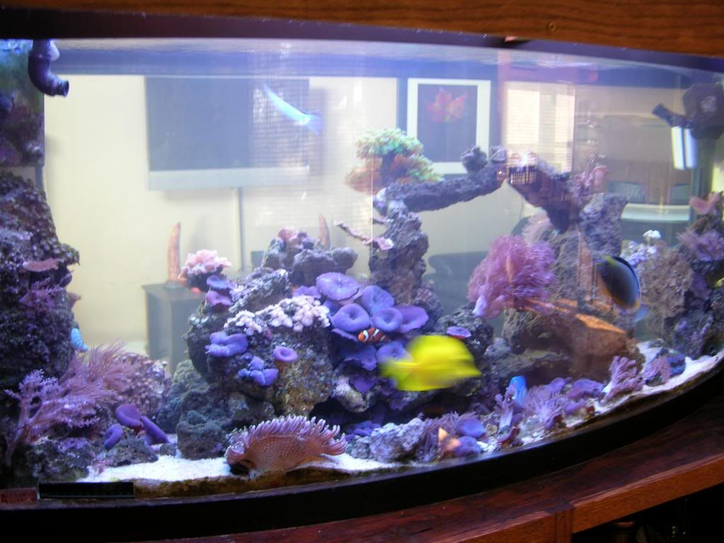
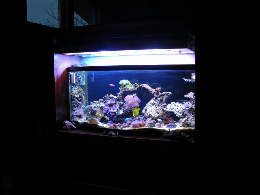
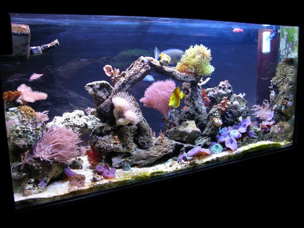
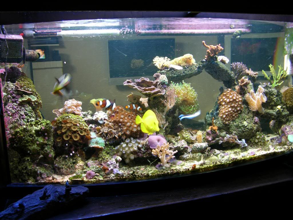
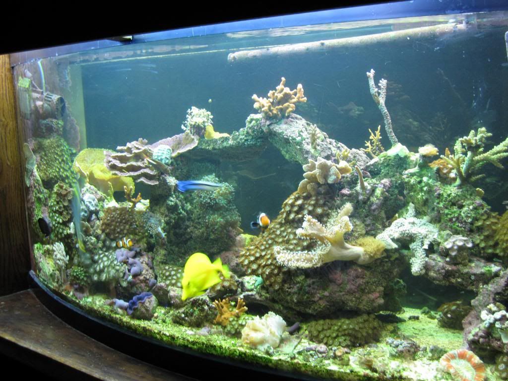
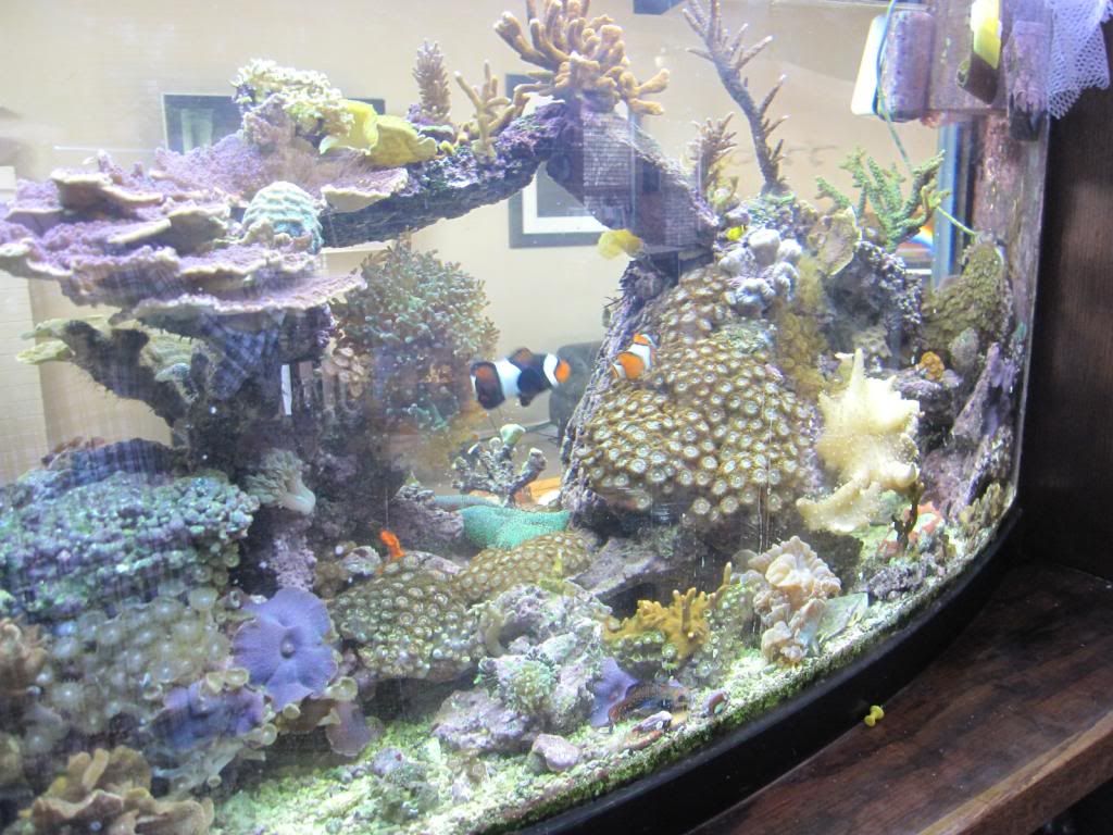
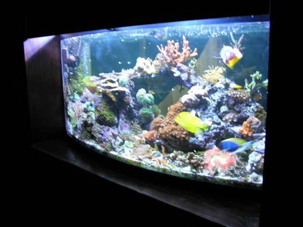
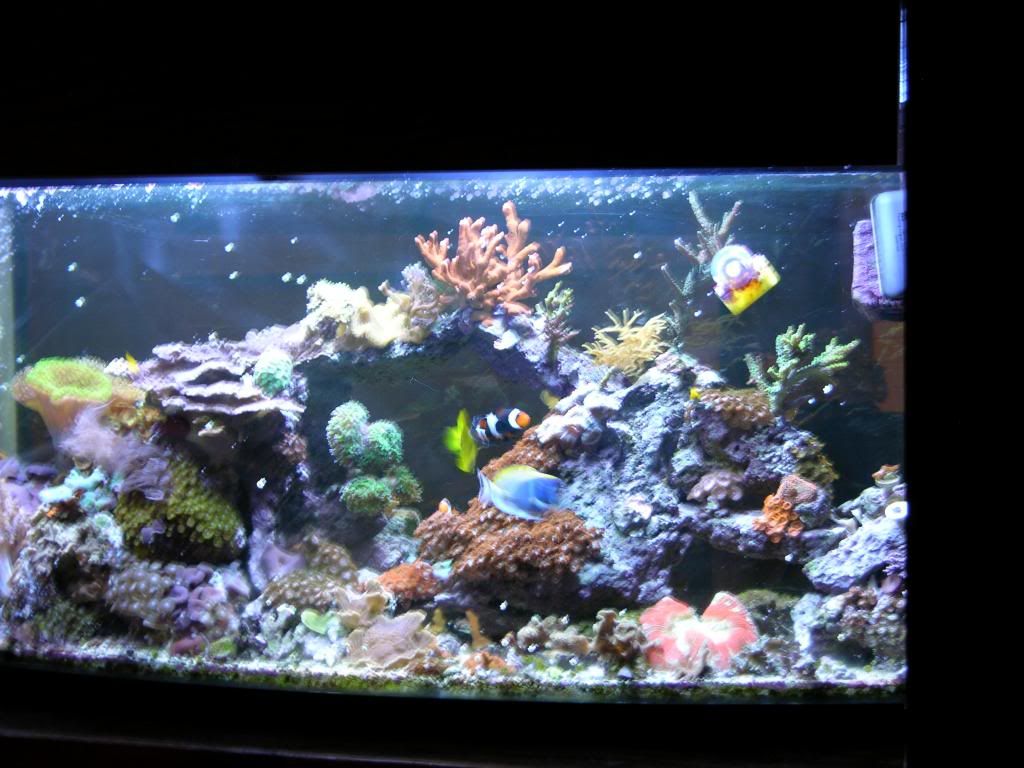
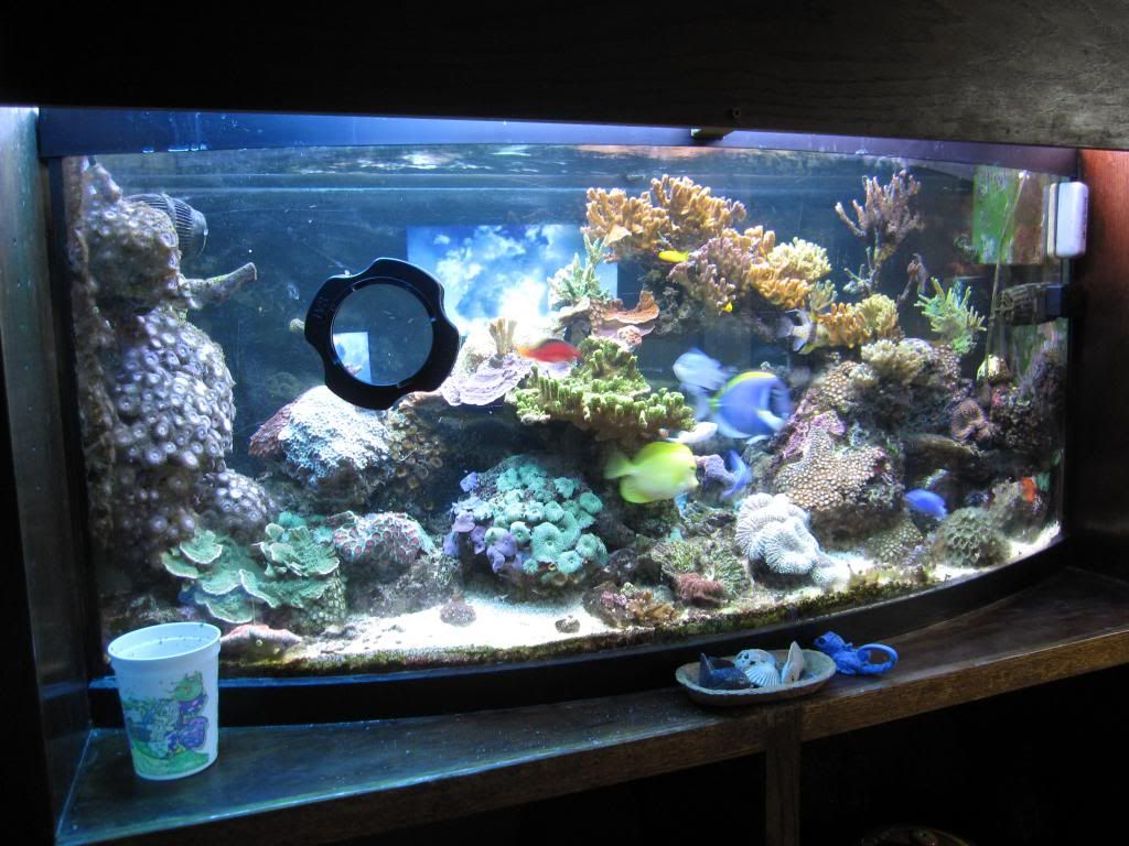
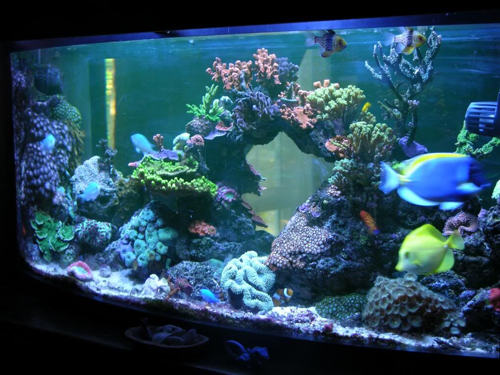
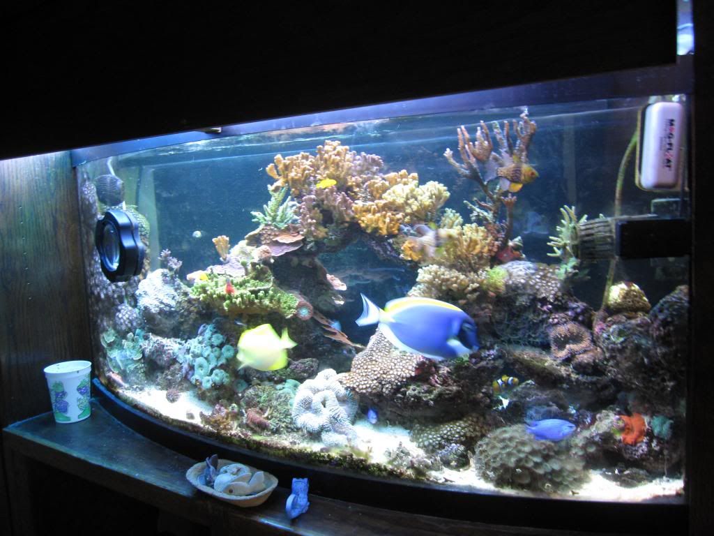
I enjoyed pulling together pictures from the begining. Here we go, starting with building up and onto this month -- tank really didn't start looking good until 2 yrs ago
2006_02-DSCN2615


2006_05-DSCN2779


2006_10-


2006_11-DSCN3415


2007_11-DSCN4826


2007_12-DSCN4687


2007_12-DSCN4693


2008_08-DSCN5300


2008_12-IMG_0036
 
Last edited by a moderator:

DyM

Sting ray
M.A.S.C Club Member
#51
2009_04-IMG_0277


2009_07-DSCN6015


2009_07-DSCN6042


2010_10-IMG_5088


2011_08-DSCN0081


2011_10-IMG_5089


2013_01_DSCN5984


2013_01_DSCN5986
 
Last edited by a moderator:

DyM

Sting ray
M.A.S.C Club Member
#53
After getting a few questions on how I dose, and about it being a cheap method, decided to expand on it here. Don't get me wrong BRS 2 part, Ionic A&B, etc etc are all great, but they'll cost you more than the "Randy's 2 part" developed by Randy Holmes-Farley (PhD Chemist from Harvard and Cornell University’s). If you have a large system, 250gal and larger, I've heard a calcium reactor route is still a cheaper way, but I don't have the experience to comment since I have but 100gal water volume.

http://reefkeeping.com/issues/2006-02/rhf/index.php

Specific items used for me are: Excel snow melt from Sam's club ($18 for 50lbs and after 5 yrs, I'm 3/4 through the bucket), Arm and hammer baking soda ($8 for a 9lb bag and I go through a pound a month), + Mag chloride from Ace (Cost $20 for 50lb bag that I purchased 3 yrs ago, but almost out) mixed with Epson salt as per the linked recipe. (Epson salt bought from Walgreens in 5lb bag, recall it costs around $20 for 6 bags.

I don't mix the ingredients in water for Calc and Alk and dose a specific ml per day, but just dump 2 tbs dry of each every day to an area of my sump. The Mag I mix with water because the ingredients absorb moisture so it gets messy if you don't mix it in water.

Let me know if you have any questions.
 

DyM

Sting ray
M.A.S.C Club Member
#57
H2O_intolerant;220772 said:
How did you figure out how much to dump in?
Each tank is different, so it takes some tuning to find your mix. You’ll find it honestly by trial and error, measuring with test kits almost daily. Once you find it though, it's not a set and forget. I measure my tank every 2 weeks, up to once per month; changing dosing amounts a little here and there. For me, I noticed two main factors that impact how much is dosed

(1) how much my tank consumes; changing naturally over time as corals grow and more is added - and (2) how many variables you have such as (2a) carbon dosing, which vinegar for example knocks down alkalinity. Also, I run a sulfur reactor, again knocking down alk. Further, I dose Lanthanum Chloride and that knocks alkalinity – all this means I probably dose 2-3x more alkalinity than someone else with similar water volume (2b) I skim wet and my skimmer takes out more some days than others. (2c) tank evaporation fluctuates during the year and water changes, each impacts the water going in/out - rather that be RO/DI or fresh salt. All these factors impact the "balance"

Given those factors off the top of my head, even what's dosed in my reef changes. I wish there were a magic receipt, or it would be truly awesome to be able to measure Calc, and Alk with probes from one of the controller companies. Yes I know Ph kind of lends itself to Alk, but I haven't found the exact connection. This would be a money maker if someone could figure and patent that.....
 

DyM

Sting ray
M.A.S.C Club Member
#58
majicmike;220774 said:
Hands down one of the best tanks I have ever seen.
WatercolorsGuy;220799 said:
Definitely 2nd that! An awesome tank.
Really appreciate that, this hobby is great. I feel fortunate to have stumbled and tripped along for so long. I tend to think playing god means we're only one day away from catastrophe. I try to enjoy looking at the tank every day since Murphy’s law and strike any of us.... at any time…
 

DyM

Sting ray
M.A.S.C Club Member
#59
This more details about my skimmer
ETSS 600:

No authorship on this material as it all came from the 30+ pages on reef central. This was my summary, and greatly helped in setting this up.
http://www.superskimmer.com/ETSS_600.htm


BIO BALLS

• There really is no optimum amount of balls in the tower. Gary (patent owner and builder of these skimmers) said you should have as many bioballs in the tower as possible, but not enough to stop air suction. The way he explained it to me is that the bioball tower is the skimmer. Water and air mix here and cause foam to push down into the box, where it then starts collecting and bubbling up into the neck and collection cup. If the water level is too high in both the mixing tower and the bubble riser, then foam production can decrease and has a hard time pushing its way to the tower. You can also risk an overflow.
• Open up the top of the towers and measure the tower with a ruler. Many (including Gary) state that a minimum of six inch clearance is needed between the injector and the top bioball. This is to allow a proper "buffer" zone of the water backing up into the tower and lowering air suction. This can cause the skimmer to surge and never reach a consistent foam head. If you have less than six inches, remove enough balls to reach this desired 6 inch measurement. After 24 hours, if that hasn't worked, open the gate valve to allow the water level in the skimmer box to drop a bit. No more than a quarter turn.
• If your pump is too weak, remove some bioballs and it will reduce friction (reduces the amount of small bubbles too, though). Too much pump, add some bioballs
• More balls would make dryer foam, less would make a wetter skimate (this is a part of the key to these skimmers)
o Talked to Gary at aetech and was told that some models of the 600 used less bioballs than others so went from 23 balls down to 13 and wow what a difference. (See how many add up to 6 inches from the top)
• Replace bio balls every year – I’m actually going to do this for the first time, as I ordered more bio balls along with a large auto waste collector make out of acrylic.
• Use heave fishing line to connect all the balls on a sting, this really helps with removing them for cleaning without having to take the whole skimmer out.

Pumps:

• ETSS skimmers need high pressure pumps. Read and heed their recommendations on their site.
• If your Gate is all the way open, and the skimmer is full (above the black box), then a gate or ball valve the output of the punp to throttle the output back or install a Smaller Pump. I installed a Ball valve on the output of my Panworld pump and adjust untill the correct water level is achieved.
• Make sure the pump is not restricted on the input, no pressure pump out there can you throttle of cut back on the input… only the output
Output:
• The output valve setting is extremely sensitive. you have to make VERY (And I really mean VERY small adjustments) at a time. If you are getting consistent dry foam, from that point you are almost set. Close the discharge valve a matter of one degree or less. (Just to the point that you just feel it move) repeat this every hour or two until you get a little wetter foam but not totally wet, and be patient it takes some time for it to react to the adjustment. If your ouput pipe is inside the water, changes in water levels will change its performance. My ATO keeps the sump at a rather constant level so I don’t have to worry about this.
• Make sure the output doesn't have a lot of pressure either give it a vent pipe of don't submerge the output too deep into the sump water.
• Talked to Gary at AE Tech. Skimmer can sit in sump as long as the outlet is not submerged more than an inch or two. So that is good.
• When the Drain line is over Three Feet, you need to install a vent Tee, per Gary Pics on his ETSS 1000 on his Web Site.
• Regarding micro bubbles, you will get a good amount initially but after the skimmer breaks in, it will be minimal. I think another user suggested using stress coat for fresh water tank to help speed up the process.
• If I didn’t mention, haha the gate valve movement between wet foam and dry foam is very very minimal, by that I mean you can barely feel it move.

TUNING:

• Be patient when tuning up to correct level of skimming, this skimmer sometime doesn't produce skimmate right away, by adjusting the output to see the skimmate right away will likely to cause too wet (or flood) skimming when it kicks in, I started with wide open output and closed it slowly until I saw the water is at the black portion (no water in the clear tube at this time), waited overnight and checked to see how much skimmate has rised up in the clear column and adjusted (closed/reduced the output) by turning the output valve slowly about 10degree turn at a time and checked back in a few hours before doing further adjustment. When the skimmer produced the right amount of skimmate over a few days, I marked the line at the output valve so I know it is the set point for my skimmer.
• When tuning, remember that 1/8th turn on the valve can mean the difference between overflowing with wet skimmate, and perfect dry skimmate.
• Clean the tower every two weeks, it’s a pain but if you let it go, that greatly affects the output (skimate) of the skimmer.
• Unlike other skimmers, the ETSS skimmers run great with wet skimmate. If they get to dry, the top section gets all hard and crusty in less than a week.
• Gradually turn it down the gate valve output of the skimmer until it doesn't overflow (a little every day). Eventually it will not overflow and you will have some skimmate. If it gets to the point that it doesn't overflow and you don't have any skimmate then close the value on the output of the skimmer a little more. There is a sweet spot there, you just have to dial it in. Also when doing these adjustments you should try to keep your pump dialed in to the same position. It will be very hard to dial it in if you are adjusting both the pump and the gate valve on the skimmer.
• Always run pump on full throttle and make adjustments from the gate valve back to the injector. Running the pump at full throttle is the way the skimmer was designed to work. Throttling it back to achieve the correct setting is the wrong way to adjust them

• The optimal application is opening the pump to full throttle and having the water line 1 inch below the black box.....not up in the riser. Take a peek at AETech's website (superskimmer.com) and click on the ETSS 1000. Gary has a clear version showing the optimal water level down in the box. Throttling the pump back should really be a last resort.
• Back pressure can cause the water level to rise, fall and repeat with every rising foam head. It's an annoying problem, but easily corrected once you understand how these skimmers work. Air must be coming into the skimmer via the injector at the top of the tower, and have an exit point which is the vacuum created by the waste line to the remote collection cup. These two holes act to create suction that pulls foam up through the skimmer. If water cannot freely leave the black box at the gate valve setting you've chosen, this will no doubt cause surging and poor skimmate production because the water level will in the skimmer will never stay constant. With this added vent pipe, the water can freely flow back to the sump with the elbows creating minimal friction due excess air having an exit point out the vent.
water level:
• To tell you the truth I never understood the directions regarding the water level. What I have learned is that if you see any water above the top of the black box the flow is either too srong or the air is too restricted. Do not pay any attention to the water level IMO.
• Let the first section of the riser fill with bubbles and adjust the valve so the bubbles just reach to the base of the second riser and wait. In about 1 hour it will be foaming all the way to the top - then adjust the valve so the foam is neither too wet (which may overflow the skimmer once there is a sudden change in water quality like when feeding) nor too dry (which will tend to create waste accumulation around the top ring.


AETech customer support.

Contact us
845-838-9044
Gary
845-227-2812
 

DyM

Sting ray
M.A.S.C Club Member
#60
Kalk Reactor

[size=+2]Kalk Reactor [/size]

I posted earlier that one of the planned changes was to install a Kalk Reactor. I put it in operation yesterday and wanted to document some of the details on the planning, calculations, research, and some of the tuning that’s going on. The reactor I have is an Aqua Medic Kalk Reactor 1000.

Over the last few weeks I’ve been testing, fixing, and modifying the reactor to fit my needs. I was initially just trying to get water through the reactor and up and over the door. That in itself took far more time than anticipated and the reason behind the modifications. First, the input is a standard RO tube with of ¼. The output is ½. Pumping water from the RO/DI reservoir through ¼ and out the ½ required a lot more powerfull pump. Before investing in a new pump, I thought it would be cheaper and better to modify the input and output to be 3/8. So I took many back and forth trips to Lowes to get the right connectors and such, and finally found a pump on hand that could handle the task. I think it’s a RIO pump, will post later on that.
I’ve dosed Kalk with a dripper on-and-off so have some familiarity with it. I however had a lot of questions that required a bit of research. The instructions say mix 2 cups in the reactor. Consulting with Mr. Google: 1 cup = 48 tsp (16 tbsp). If I understand the articles & posts correctly (Google searches), 2 tsp per gallon will create saturated slurry.

So my rational is this for a kalk reactor - per one gallon of RO that passes through the reactor consumes 2 tsp of the lime. 1 cup = 48 tsp, so technically, 1 cup should last 24 days (again assuming 1 gallon is what I'd need but this is simply a calculation to ballpark when I need to either add more calc, or clean out the reactor and add a new fresh batch). How did I come up with 1 gal per day? Honestly a complete guess and a starting point. I’ve dosed 2 liters of Kalk and it doesn’t dent how much two part I need to dose so just decided to double that, and adjust from there. I may end of doubling this amount, or just keep it at 1 gallon and put in 2 part as needed to finish the daily consumption.

To determine if the Kalk was exhausted, my initial thought was to measure the ph to ensure it’s at 12.4 – because that is what saturated slury should measure. Upon more research, a conductivity meter with the proper range is a more accurate way to measure if the reactor needs more or replaced Kalk. Randy Homes has an article that states to ensure your probe/meter can read in the 5-12 mS/cm range.… a conductivity of 7 mS/cm, indicates the slury is not saturated (saturated limewater usually has a conductivity of about 10.3 mS/cm at 25 deg C). I have a conductivity probe for the Neptune apex but the reactor or inline is set up for this so it’s a future possible project. Also, one of the issues I need to address is my RO water, and where the Kalc reactor is - is nowhere near 25 Celsius (77 Fahrenheit) so I'll have to experiment what lower temps do to the conductivity. That is why I used a dry measurement and what amount saturates it, and measure how much water passes through the reactor.
For reference, I've found a lot of different interpretations of defining the amount of tsp or tbsp that "saturates" Kalc (without vinegar) per gallon. From the best of what I've found from Randy is: "Saturation is about 2 level teaspoons of lime per gallon of fresh water. Any more will just settle out as mud on the bottom." http://www.reefcentral.com/forums/sh...ductivity+kalk

I found some useful info here about approx how long a cup lasts and a few techniques:
http://www.reefcentral.com/forums/sh...ductivity+kalk

More references:
http://reefkeeping.com/issues/2003-0...ture/index.php
http://reefkeeping.com/issues/2005-01/rhf/index.php
 
Top